
A tiny game console based on Attiny85

Okay, the first thing first! I am a big-time retro games fan, it reminds me of my good old days when I used to play Mario on my super famicom. But this DIY project is not related to retro games, you can’t play 8-bit retro games. But what you can do is either code your own game or play games which are already created for Attiny85 by Daniel Champagne
I had some Attiny85 laying around my desk and I was kinda free for some days, so I started searching for some projects related to this tiny chip and I found that Daniel already created some games for this, Nice!!! So I downloaded his project and started to look around. The schematics which he shared had some issues and values for some resistors were missing. To get this working, I tried to contact him via email and he quickly replied to me with the details which I was looking for.
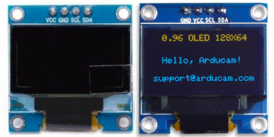
The next step was to create the prototype for the game console and test out things. I started with testing the OLED screen which was required for this project and it was SSD1306 based 4 pin I2C screen. Luckily I had some of those as well in my lab, so I started to compile his code.
The code which Daniel wrote depends on a library for SSD1306 known as ssd1306xled, which is hosted on Github at https://github.com/Defragster/ssd1306xled. I downloaded this dependency and wrote some test code that compiled fine, but there was no output on the screen. I was not sure what went wrong, so I tried with a few other SSD1306 screens which I have and none of them worked. Now to be sure that my screen works, I used the Adafruit library for SSD1306 and it worked like charm, all of my OLED screens are fine and working as expected. Now, this is something that I was not expecting from the ssd1306xled library, so I started to search Google for some answers. The library which is hosted on Github was a port of AVR TinuSaur project, and the original version of this library is hosted at https://bitbucket.org/tinusaur/ssd1306xled/src/default/ and the original version was recently updated.
A few more searches related to this library took me to the website of Tinusaur and I found an article describing some compatibility issues. So the thing is that most of the OLED screens come from China which claims to be using SSD1306 but may not use SSD1306. Instead, sometimes they use SSD1315 or SSH1306. So to get things working, I cloned the original SSD1306XLED repository and modified the code to work with my Attiny85 and yet it was not working. Further digging into the issue and code led me to the conclusion that something was not right with the I2C implementation of the library itself. You can check my journey on the issue which I created here
The Attiny85 chip comes with 8KB of flash memory, so there’s not much room to fit the code. The game is around 6KB, which leaves us with 2KB of memory for the OLED screen driver and hence if I use some other OLED driver library like Adafruit’s or Tiny4kOled then resulting (program) will cross this 8KB limit and hence I won’t be able to fit this into my chip.
To get around this issue, I modified the latest SSD1306XLED library and replaced the I2C implementation with the working I2C implementation from TinyI2C, I carefully picked the required codes and bingo! It worked!!!
You can find the working implementation on my github repository
Now it’s time to check the actual schematic from Daniel and while I was searching for the solutions related to OLED screen, I came to know about a project by Dave, posted in element14 community. The post was a modification of original implementation by Daniel, especially the optimized use of Attiny85 pins. If you are interested in this project and reached this far, I strongly recommend you to watch the video by Dave posted on the element14 community.
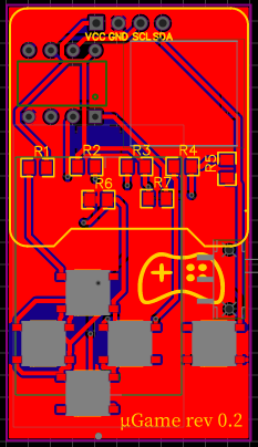
Okay, enough talk. Let’s move with the PCB design, the motto was simple. Make this project as small as possible and use SMD components. For the resistors, I prefer to use 0805 sizes, its not too small to solder and not too big to take a lot of space.
For the quick implementation and simple projects, I prefer to use EasyEDA over Altium. To start the project, I first needed to choose SMD components and gather their footprints so that I can design the PCB accordingly. Below is the list of required components with their manufacturer part number, you can order them on element14, digikey or mouser.
| Quantity | Manufacturer Part Number | Manufacturer Name | Notes |
|---|---|---|---|
| 1.0 | ATTINY85-20PU | MICROCHIP | Attiny85 IC |
| 5.0 | SKQGAFE010 | ALPS ALPINE | Push button |
| 2.0 | MCWR08X2001FTL | MULTICOMP PRO | 2K resistor |
| 2.0 | WR08X1002FTL | WALSIN | 10K resistor |
| 1.0 | MCPWR05FTEW8201 | MULTICOMP PRO | 8.2K (8K2) resistor |
| 1.0 | ERJ6GEYJ392V | PANASONIC | 3.9K (3K9) resistor |
| 1.0 | MCWR08X1802FTL | MULTICOMP PRO | 18K resistor |
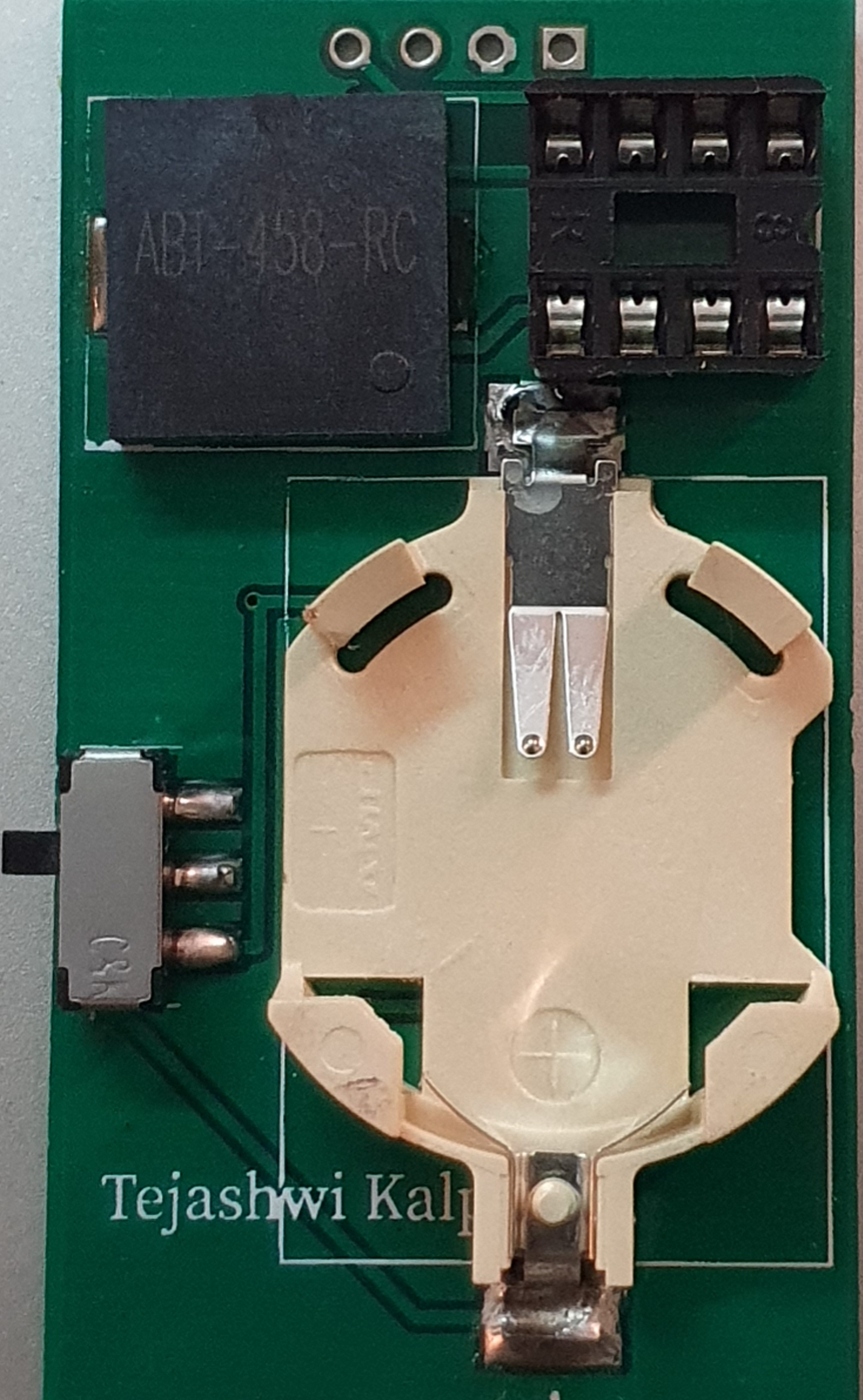
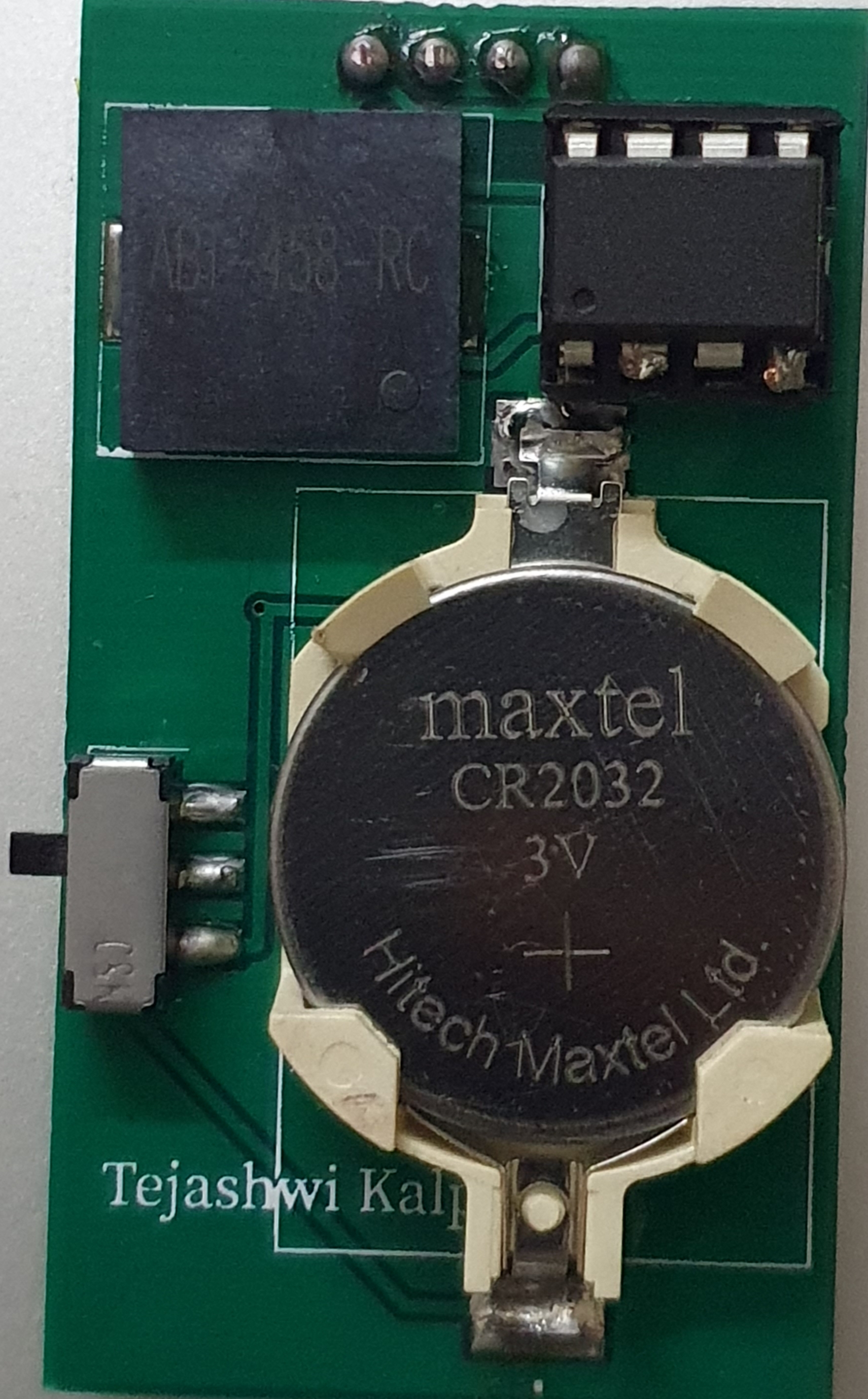
| 1.0 | MCABT-458-RC | MULTICOMP PRO | Speaker |
| 1.0 | 796136-1 | TE CONNECTIVITY | CR2032 battery holder |
| 1.0 | JS102011SAQN | C & K COMPONENTS | Power switch |
| 1.0 | SSD1306 | 0.96 inch white OLED screen |
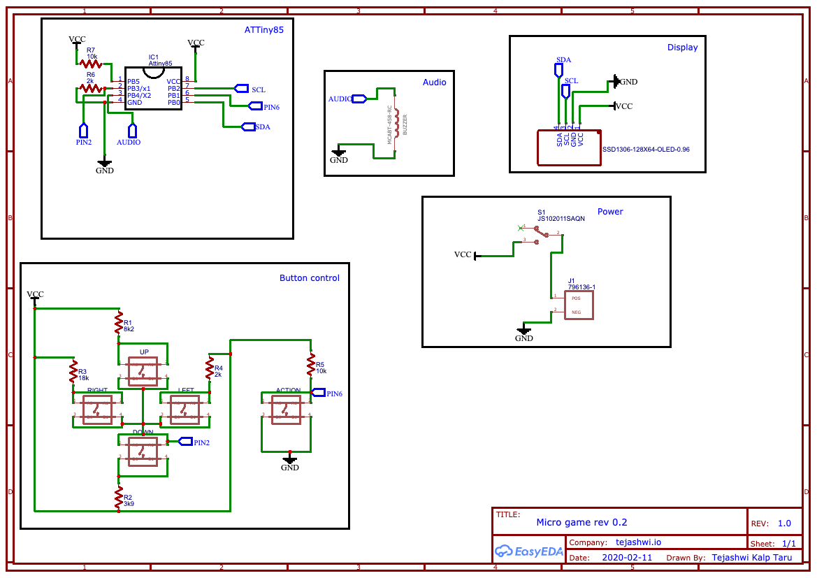
Using these parts and schematic from Dave as a reference, I created my schematic and PCB. Thanks to Daniel and Dave for their creativity 😉

I placed the order to get the PCB fabricated and now I needed to wait for around a week to get the PCB delivered. During this free time, I noticed a mistake which I made. Again with the OLED screens!
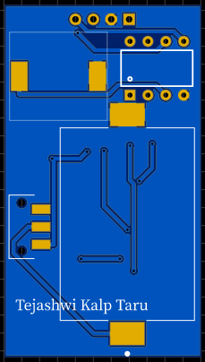
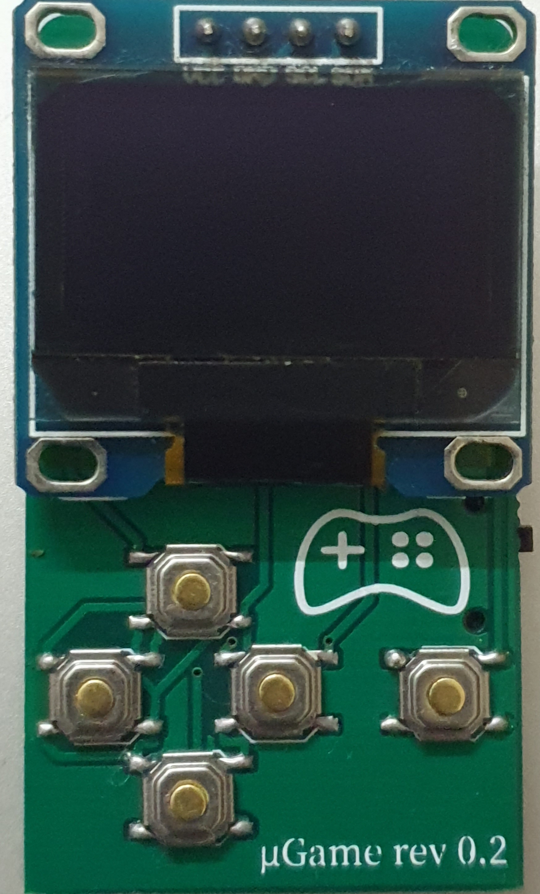
If you look closely to the PCB design posted above, you can see the order of OLED pins are VCC-GND-SCL-SDA, but some of the OLED screens come with first 2 pins swapped 🤦♂️
This can be fixed by making some trace cutouts and adding small jumpers to the PCB (which we designed NOT the OLED screen PCB, OLED screens are fragile, do not try to modify), but just for you guys out there who wanted to try out this project, I made some modifications to my schematic and added pads so that regardless of the OLED first 2 pins, you can solder them to match screen configuration.
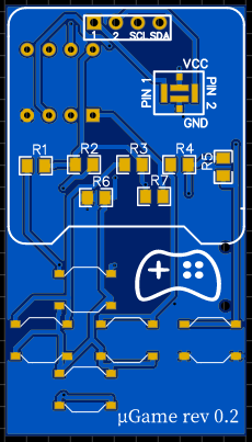
Look closely, you can see that I renamed the first 2 pins of OLED to 1 and 2, and there is a box with 4 pads to configure. So if your screen is VCC-GND then connect PIN1 to VCC and PIN2 to GND and vice-versa.
Here’s the comparison of both the design
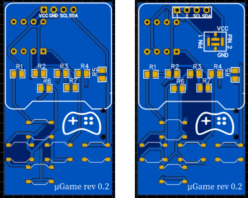
Let’s provide a name to both the designs
- Design A (specific for OLED screens with pin order
VCC-GND-SCL-SDA) - Design B (can be used for OLED screens with pin order
VCC-GND-SCL-SDAorGND-VCC-SCL-SDA)
After a week, PCB and the components were delivered, and its time to build the gem.
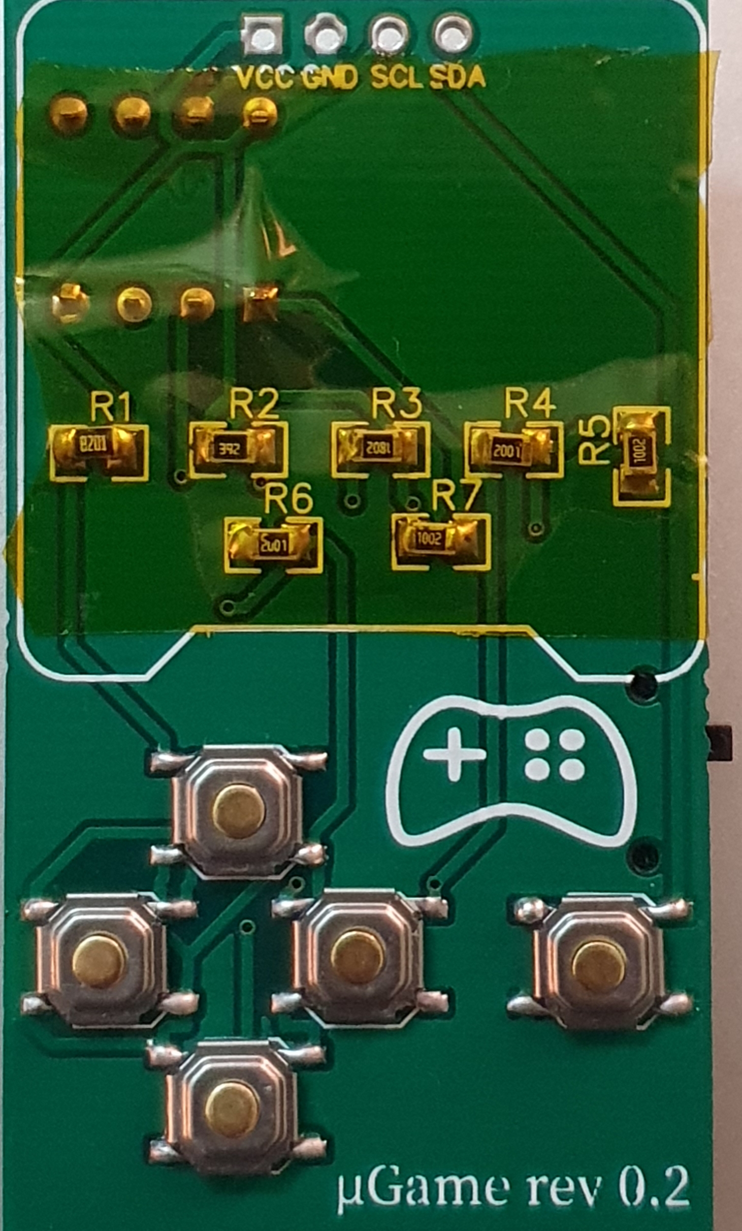
Because the control keys (up/down/left/right) are connected to PIN 2 (A3) of the Attiny85 and in the code analogRead function is used to read the value and determine which button is pressed, we might need to find out proper values for each of the button press, expect the action button. For this, I used a small function and whenever I press any of the control keys, its analog value will be displayed. This is a crucial step to properly modify the code to work with our implementation, as the value of analogRead can depend on lots of factors.
1
2
3
4
5
6
7
8
9
10
11
12
13
14
15
16
void setup() {
    _delay_ms(40);
    SSD1306.ssd1306_init();
}

void loop() {
    _delay_ms(500);
    SSD1306.ssd1306_fillscreen(0);
    int value = analogRead(A3);
    if(value > 0) {
        char buf[20];
        sprintf(buf, "value: %d", value);
        SSD1306.ssd1306_setpos(0, 1);
        SSD1306.ssd1306_string_font6x8(buf);
    }
}
From my experiment, the values are:
- UP => 180 - 250
- DOWN => 300 - 400
- LEFT => 90 - 110
- RIGHT => >400
Adjust these values in the game (you can find the control checks in the loop function), compile and burn it to Attiny85.
To burn the code to Attiny85 you can use Arduino as ISP or use USBAsp programmer. Describing here how to perform this, is a story for another post. Meanwhile, you can search Google, there are lots of tutorial for that.
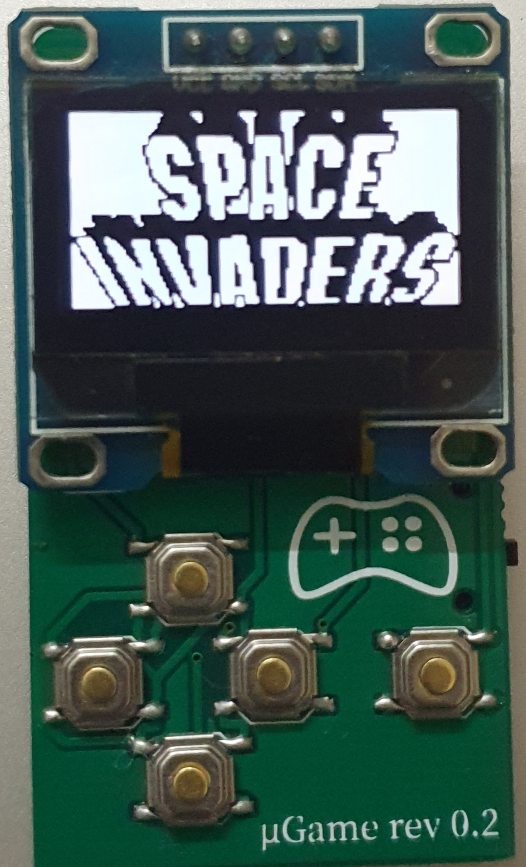
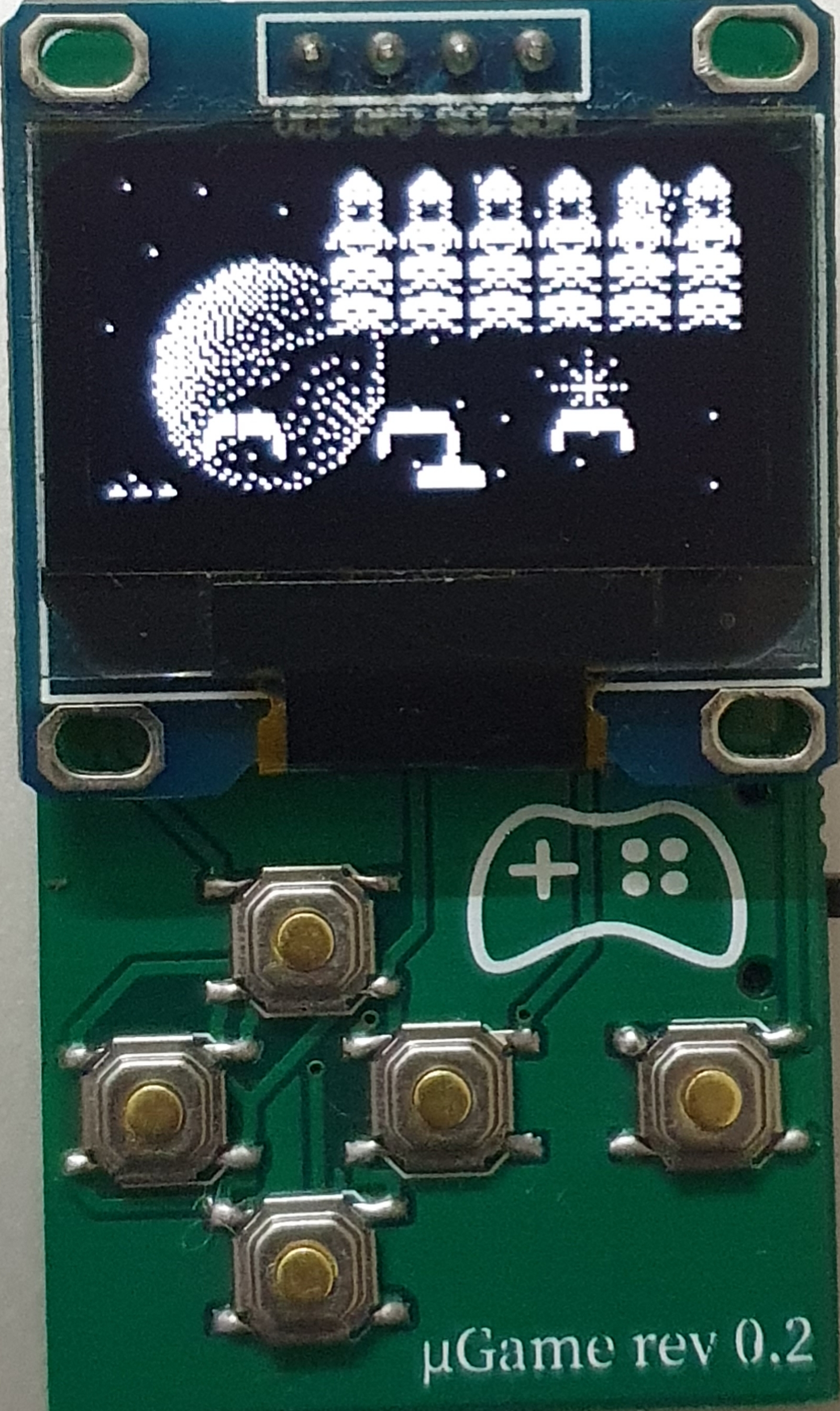
And bingo here’s my tiny game console
Downloads